The front screen
The help for this page of the Version 2 transmitter, in its newest words. A transmitter on V2 B92 or older shows older words.
On the transmitter: Front screen
The front screen: keep it, or your own front screen, in view while you fly. It shows the bank, rate, time, trims, motor timer and batteries.
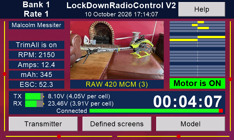
'Transmitter' and 'Model' (bottom corners) open the setups.
'Defined screens' (bottom middle) shows your own front screen instead, with your choice of numbers, big and clear.
Its 'Original screen' button brings this screen back.
Your choice stays through take-offs, landings and switching off, until you press the other button. Design your own screens in Transmitter setup / 'Appearance' / 'Defined front screens'.
Touch the model's picture to choose another picture.
With Rotorflight, touch the RPM box to open 'Rotorflight options' (put the safety on and the motor off first).
With a model connected, switching the motor on brings the front screen back from any other page. Not while a question is waiting, or you are a buddy pupil, or during a calibration, a scan, or a Rotorflight backup or restore.
Left column
At the top, your name ('Owner's name', Transmitter setup / 'System'). Under it, notes:
AMS is on (or off): when a receiver connects, the transmitter finds its model by itself ('Automatic model selection (AMS)', Transmitter setup / 'System'). Shown until a model connects.
'Trims: all banks': a trim change goes to every bank ('Copy trims to all banks', Model setup / 'Options').
With Rotorflight: head speed (RPM), current (Amps), capacity used (mAh) and the ESC temperature (ESC).
Battery LOW: see Batteries (bottom left) below.
MOTOR IS ON! (only with 'Use motor kill switch' on): the motor switch was on at switch-on, or when the link was lost.
Nothing is sent to the model until you switch the motor off and press 'OK' on the message 'The motor switch is ON.'
Model name (under the picture)
The number after the name is the model's number, as in (3).
Square brackets, as in [3], or [AMS is on] on the left, mean this model has no stored ID yet ('Model IDs', Model setup).
Channel bars (top right)
Channels 1 to 16, in groups of four. Each bar grows from the middle line: to the left below centre, to the right above.
Under the bars, the Motor box. With 'Use motor kill switch' on (Model setup / 'Options'), it is red while the safety is on, and green while it is off.
Motor timer (the big numbers)
It runs while the motor is on, and pauses while it is off.
It starts again each time a model connects.
With 'Timer voice' on (Transmitter setup / 'Sounds etc.'), each whole minute up to ten is spoken.
To count down instead (Model setup / 'Options'): turn on 'Timer counts down' and set 'Count down from (minutes)'.
The last ten seconds are counted aloud. With 'Timer voice' on, you hear 'Stop flying!' at zero.
Batteries (bottom left)
TX is the transmitter's battery, RX the model's. Each shows a bar, the total voltage and the voltage PER CELL.
Why per cell? Most pilots know at once the cell voltage a pack should not go below: about 3.6 volts for LiPo and Li-ion.
The transmitter battery always has 2 cells: LiPo, Li-ion or LiFePO4. Set its type, and the number of cells in the model's battery, on the 'Batteries' page (Transmitter setup or Model setup). The bars, cell voltages and warnings all use them.
When a battery is low, Battery LOW shows and you hear a warning:
- transmitter: at the 'Transmitter battery low at' per cent (Transmitter setup / 'System');
- model: 'Stop flying!', when a cell is below 'Stop flying volts (per cell)' (Model setup / 'Options').
About 3.6 volts is a good start.
Link quality (the bar beside 'Connected')
Green is the share of data packets that arrived, red the share lost, over the last 1 to 6 seconds. Set the seconds in 'Connection quality measured over' (page 3 of 'System').
Trims
The yellow lines down the sides and along the bottom are the four trims. The red dot shows where each trim is.
They, and the 'Trims:' note, are hidden while 'Trim multiplier (0 = off)' is 0 (Model setup / 'Options').
Light on the transmitter (LED)
Blue = the radio is not trying to connect.
Red = the radio is trying to connect.
Green = the radio is connected.
Blinking = binding is enabled.
Power button
With no model connected, one press switches the transmitter off.
With a model connected, the front screen comes back, and you must hold the button down while a countdown runs (TURN OFF?!).
This guards against a knock in flight. Set the seconds in 'Hold power button for' (page 3 of 'System').
Questions
If the help screens leave a question unanswered, please email Malcolm Messiter at mmessiter@gmail.com
Still stuck?
See common questions, or write to mmessiter@gmail.com. Say which page, and what the screen showed.