The Rotorflight dongle
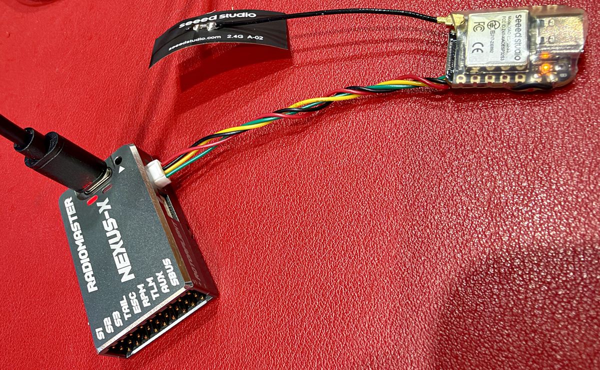
The phone app on any Rotorflight helicopter, whatever receiver flies it. One small board, four wires.
This tiny dongle sets up a Rotorflight helicopter from your phone, without the official Configurator. It does almost everything the Configurator does. Only flashing Rotorflight itself needs a computer.
- It puts set-up and tuning into a sensible order, ticked off as you go.
- It speaks plain English. Press and hold an underlined word to see what it means. Every page has its own help.
- It is also a simulator interface: it turns a receiver into a USB joystick for your computer.
- The app is free for iPhone and iPad (App Store) and Android: see Phone Apps.
In a hurry? It all fits on one page: the one-page guide, or print it as a PDF to keep with the model.
What it does
- Wizards for a new helicopter and for tuning: each job in order, each step ticked off. À la carte goes straight to any one setting.
- Easy tuning: the sliders that matter, in one place, in plain words. All six banks (profiles), and a choice of how many you use.
- Copy a bank in one tap, read back and checked. Park a tune you like in a spare bank before an experiment.
- Back up and restore the tune and set-up, every bank, to the phone (not ESC, ports, LED or GPS). Share a backup with a friend: their tune, not your servos.
- Read the black box and check the filters after a flight, with advice in English.
- Search for any setting by the word you would use.
- Updates arrive by themselves. The app offers new dongle software when there is some, and installs it over Bluetooth at the field or over WiFi at home. It also tells you when a new Rotorflight is out, and to back up first.
One app, one software. The same board with radio modules fitted is the LockDownRadioControl receiver, which does all of this and flies the model. The dongle knows it is a dongle because it finds no radio when it starts.
What you need
- A dongle: a Seeed XIAO ESP32-S3, with the software in and its four-wire lead soldered on, ending in the plug that fits a Nexus-X port. I have loan dongles (ask me for one), or make your own: one small board, four wires, and the software from your browser.
- A short USB-C cable, if you go the USB way. A Chenyang CY-UC-088-0.07M is ideal: 70 mm, flat, right-angled at both ends. Any short one will do, so long as it carries data as well as power. Many short leads only charge.
- A Nexus-X port B or C. Not port A: that is usually the receiver's, and the receiver that flies the model needs it. Both are printed RX TX + − and give 5 V. On other flight controllers, any spare UART with 5 V.
- The RXV2 app: iPhone and iPad from the App Store; Android from the Phone Apps page.
How to use it
Safety: blades off
Take the blades off, or unplug the motor, before you touch anything in the app. Setting up is done on the bench, never with the rotor turning.
Power
While the dongle is wired to a flight controller, power it only from the flight controller, through its lead. Never plug a computer, phone charger or power bank into its USB socket then. The dongle drives the USB cable, so it puts 5 V down it. Most flight controllers feed USB power into their own 5 V rail, so a second supply would meet the flight controller's head-on. (Flashing and simulator mode: flight controller unplugged.)
-
Plug the lead into a spare UART
On a Nexus, port B or C, not A.
-
Add the USB cable, if you have one
From the flight controller's USB socket to the dongle's. Short, and one that carries data. By USB there is nothing to set, and the app does almost everything the Configurator does.
-
No USB cable? Set the port once
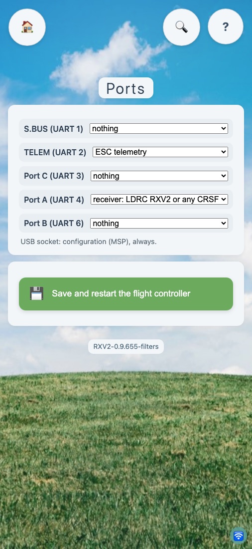
Most things still work by the lead alone. A few need USB: the black box, the command line and a factory reset. Rotorflight has to be told where the dongle is: set that port to MSP 115200, in the official Configurator, or in the app's own Ports page if you can borrow a USB cable for the first visit.
-
Open the RXV2 app
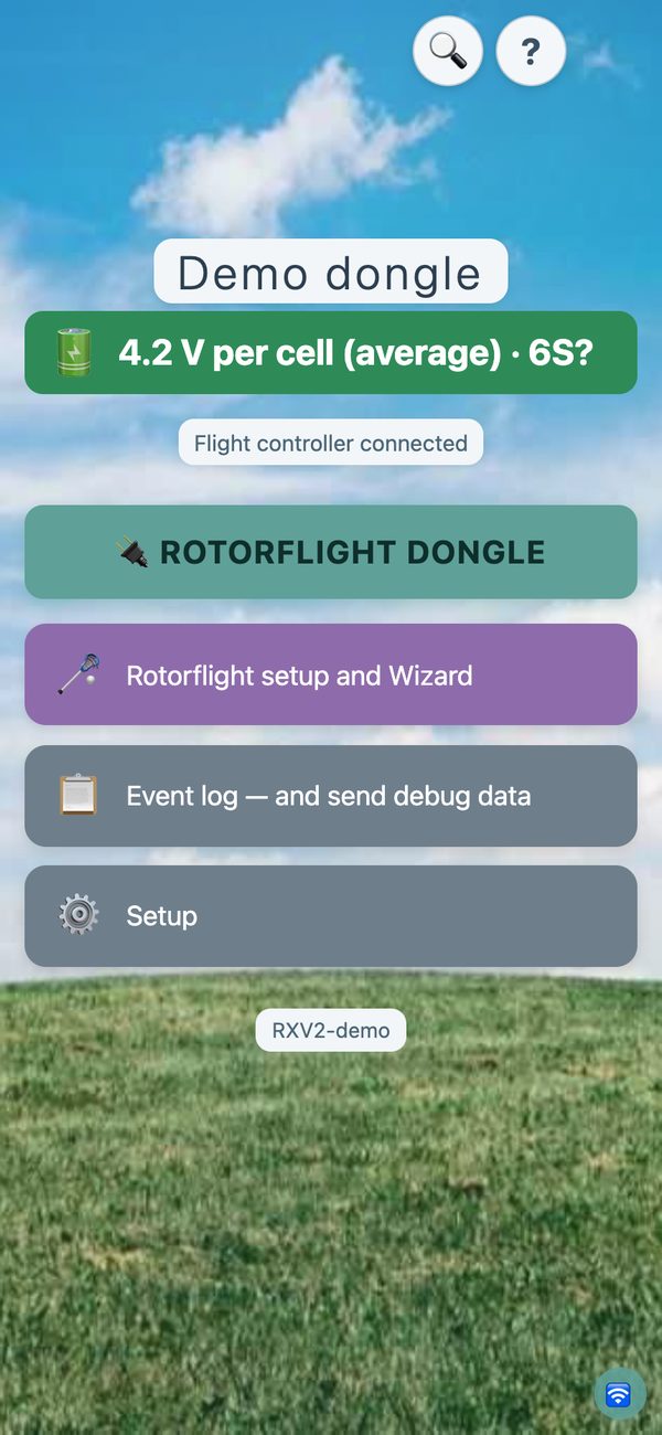
It searches for dongles and receivers nearby. Tap yours and follow what the screen says. If it finds none, it offers a demonstration, so you can see the whole thing before you buy a single part.
-
At home, give it your WiFi
Setup → WiFi. Everything is quicker over WiFi. At the field it uses Bluetooth alone, and needs nothing else.
Safety while flying
The dongle asks the flight controller, several times a second, whether the model is armed. The moment it is, the app refuses to change anything and the dongle switches its Bluetooth and WiFi off, so nothing can interfere with the radio link. (A LockDownRadioControl receiver watches its own arming channel and does the same.)
On a Nexus, the Ports page names the sockets as printed on the board: Port A, Port B, Port C, TELEM and S.BUS. Other boards show the socket numbers printed on them (UART 1, UART 2 and so on).
Simulator interface
The same dongle connects one of your receivers to a simulator on the computer, Windows or Mac.
-
Choose the role
In the app, on the dongle's Role card, choose Simulator interface.
-
Move the lead to the receiver
The receiver's signal output to D5, its 5 V to the dongle's 5V pin, ground to ground.
-
Plug the dongle into the computer
The USB cable powers the whole rig: no battery, no flight controller. The computer sees a joystick.
It recognises CRSF, SBUS, IBUS and PPM by itself. The app says which it found and how many channels arrived. Stick-to-axis mapping, reversing, the spool-up realism and the camera keys are on the app's Simulator pages.

A LockDownRadioControl receiver needs none of this: it plugs into the computer on its own and flies the simulator from your own transmitter. This role is for someone else's receiver, or for when all yours are in helicopters.
Like it? The receiver needs no dongle
The dongle is the little brother of the LockDownRadioControl receiver: the same brain with the radio fitted. The receiver does everything on this page and flies the model, so there is no dongle to fit and no spare port used up. It updates itself over the air, and flies a simulator from your own transmitter.
The whole system is free and open source: about £35 of parts for a receiver, and from about £120 in parts for a transmitter (approximate). The Version 2 receiver works with the Version 1 and Version 2 transmitters.
The port and its pins
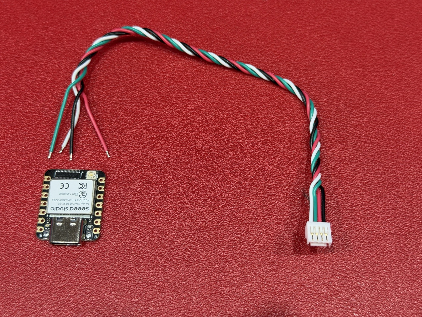
The dongle's lead carries the same four pins as the Nexus port, in the same order, so it plugs straight in. Building your own? This is the order, printed on the Nexus-X left to right with EXT-V on the left:
| Nexus port pin | Signal | XIAO pin | Wire on the Nexus lead |
|---|---|---|---|
| RX | Flight controller listening | D6 | White |
| TX | Flight controller talking | D5 | Green |
| + | 5 V from the flight controller | 5V | Red |
| − | Ground | GND | Black |

Easiest of all: use the four-way lead that came in the box with the Nexus. One end already carries the plug that fits the port. Strip the four bare ends and solder them to the board: white to D6, green to D5, red to 5V, black to GND.
Check the colours on your own lead
Those four are right for the lead that came with my Nexus. Another may be wired differently, and leads from other suppliers certainly are. Read the pin labels beside the port, or the manual, and check with a meter before the first power-up. Getting + and − the wrong way round can destroy the flight controller.
Build it with four wires, not the circuit board
Do not order the dongle circuit board in the repository (RXV2/kicad/dongle). Its first batch had the plug wired wrongly: it put 5 V onto a signal pin and destroyed two chips. Four wires are all a dongle needs.
FlyDragon Pro: use the GPS port
On a FlyDragon Pro, use the six-pin GPS port on the end of the case: everything on one plug, and its 5.0V pin is regulated.
Do not take power from RX2/TX2
Like the servo pins, their + carries whatever the ESC's BEC gives, often 6–8.4 V, which would destroy the dongle. (RX2/TX2 can still carry the two signal wires, or use a 5 V regulator such as a Pololu S9V11F5 in the + lead.) A LockDownRadioControl receiver built on its circuit board has its own regulator, so RX2/TX2 power suits it. Those board files are not published yet. A hand-wired receiver has no regulator: treat it like the dongle and use the 5.0V GPS port.
| FlyDragon GPS port | Board pin | On my lead |
|---|---|---|
| 5.0V | 5V | red → red |
| RX5 (the FlyDragon listens) | D6 | white → green |
| TX5 (the FlyDragon talks) | D5 | green → white |
| SCL, SDA | — | not used |
| GND | GND | black → black |
- The rule, whatever the colours: the controller's RX goes to D6, its TX to D5.
- The plug is a 6-pin JST-GH (1.25 mm). Buy it ready-made with leads and cut off SCL and SDA. Go by the pin names printed on the case, not by wire colours, and check the 5.0V pin reads 5 V on a meter first.
- Using RX2/TX2 for the signals is the same rule (RX2 to D6, TX2 to D5), and the port is UART2.
- Then in Rotorflight, Ports tab, UART5 (or UART2): MSP at 115200 for a dongle; or Serial RX for a LockDownRadioControl receiver, with the receiver type set to CRSF. (The FlyDragon's own receiver is on UART1.)
Set the BEC to 6 V or more
The FlyDragon's own 5 V needs a higher voltage going in. Fed only 5 V by the BEC, everything stopped working once the USB cable was connected; at 8 V it was fine. Most helicopter BECs already run at 6–8.4 V.
Making your own: the software
The dongle is a bare Seeed XIAO ESP32-S3 and four wires: the pin table above is the whole of the wiring. This is how to put the software in.
Fit the aerial
The little aerial in the box presses onto the tiny gold socket on top of the board. Without it, Bluetooth and WiFi reach about an arm's length. Easy to forget; I did.
Use a data cable
You need a USB-C cable that carries data, not just power. A charge-only lead is the commonest reason a new board never appears.
The easy way: one click, in your browser
Plug the chip into a computer, open the flasher and press one button. The browser writes the software straight in: nothing to install, nothing to download. It erases as it goes, so the same button also puts a used board back exactly as new.
Flash a chip from your browser
Chrome, Edge or Opera, on a desktop or laptop. Safari, Firefox and phones cannot do it.
By hand: five ready-made files
Only if you would rather do it yourself, or your browser cannot. Nothing to compile. Works on Mac, Windows and Linux.
-
Install esptool
Espressif's flashing program. With Python already on the computer:
pip install esptool -
Download the five files
Into one folder. They are always the current release:
- bootloader.bin
- partitions.bin
- boot_app0.bin
- firmware.bin
- littlefs.bin (the app's own pages)
-
Put the board into flashing mode
Plug it in. Hold B, tap R, let go of B. The yellow light goes out when it has worked. (A red light may stay on: that is the charger; ignore it.)
Do it every time. A board that already has our software takes the USB socket for its own use, so no port appears without the buttons. The port then shows as
/dev/cu.usbmodem…on a Mac, orCOM3or similar on Windows. -
Write all five in one go
From that folder. Put your own port in place of the one here:
esptool --chip esp32s3 --port /dev/cu.usbmodem101 --baud 921600 write_flash -z --flash_mode dio --flash_freq 80m --flash_size 8MB 0x0 bootloader.bin 0x8000 partitions.bin 0xe000 boot_app0.bin 0x10000 firmware.bin 0x670000 littlefs.binCheck: every one of the five reports "Hash of data verified". If one does not, run it again.
The addresses matter
littlefs.bin at 0x670000 holds every page you see in the app. Leave it out and the dongle runs, but its screens are blank.
If the board never appears as a port
Try a different USB-C cable first: the orange charging light comes on even with a charge-only lead, so power is no proof of data. Then do B and R again.
Or build it from the source
Everything is free on GitHub: github.com/Mmessiter/LDRC_V2. The receiver and dongle software (GPL-3.0-or-later) is the RXV2 folder: one program does both jobs. Install PlatformIO and Node.js. Do B and R before each of the two upload commands, and put your own port in place of the one here:
git clone https://github.com/Mmessiter/LDRC_V2.git
cd LDRC_V2/RXV2
pio run -e xiao_s3_usb -t upload --upload-port /dev/cu.usbmodem101
pio run -e xiao_s3_usb -t uploadfs --upload-port /dev/cu.usbmodem101
The first command writes the program, the second the app's pages. On Windows the port is COM3 or similar.
Then: first switch-on
-
Unplug it and plug it back in
The USB port then goes quiet. That is normal, not a sign of failure.
-
Name it
Open the phone app and tap Connect: the new board is in the list as Untitled. Rename it at once, because two boards with the same name cannot be told apart. Or join its own WiFi network, Untitled, from a computer and open 192.168.4.1.
-
Nothing else to configure
A board with no radio chips works out what it is. Wired to a flight controller it is a dongle. Fed a receiver's signal on D5 it is a simulator interface. After this it updates itself over the air: you should not need a cable again.
What a dongle cannot do
It has no radio, so it does not fly or bind, and it keeps no flight records. View channels still shows the sticks, as the flight controller sees them. Almost everything for setting up and tuning Rotorflight is there.
Want the rest as well?
The LockDownRadioControl receiver does everything the dongle does and flies the model: radio link, telemetry on the transmitter, flight records, and the simulator from your own transmitter with no dongle at all.
A dongle and a receiver can both be wired to one flight controller. Connect the phone to only one of them at a time.